- 您现在的位置:买卖IC网 > Sheet目录1917 > DSPIC30F4011-30I/ML (Microchip Technology)IC DSPIC MCU/DSP 48K 44QFN
2010 Microchip Technology Inc.
DS70135G-page 159
dsPIC30F4011/4012
21.3.1.1
POR with Long Crystal Start-up Time
(with FSCM Enabled)
The oscillator start-up circuitry is not linked to the POR
circuitry.
Some
crystal
circuits
(especially
low-
frequency crystals) have a relatively long start-up time.
Therefore, one or more of the following conditions is
possible after the POR timer and the PWRT have
expired:
The oscillator circuit has not begun to oscillate.
The Oscillator Start-up Timer has not expired (if a
crystal oscillator is used).
The PLL has not achieved a lock (if PLL is used).
If the FSCM is enabled and one of the above conditions
is true, then a clock failure trap occurs. The device
automatically switches to the FRC oscillator and the
user can switch to the desired crystal oscillator in the
trap ISR.
21.3.1.2
Operating without FSCM and PWRT
If the FSCM is disabled and the Power-up Timer
(PWRT) is also disabled, then the device exits rapidly
from Reset on power-up. If the clock source is FRC,
LPRC, ERC or EC, it will be active immediately.
If the FSCM is disabled and the system clock has not
started, the device will be in a frozen state at the Reset
vector until the system clock starts. From the user’s
perspective, the device will appear to be in Reset until
a system clock is available.
21.3.2
BOR: PROGRAMMABLE
BROWN-OUT RESET
The BOR (Brown-out Reset) module is based on an
internal voltage reference circuit. The main purpose of
the BOR module is to generate a device Reset when a
brown-out condition occurs. Brown-out conditions are
generally caused by glitches on the AC mains (i.e.,
missing portions of the AC cycle waveform due to bad
power transmission lines, or voltage sags due to exces-
sive current draw when a large inductive load is turned
on).
The BOR module allows selection of one of the
following voltage trip points (see Table 24-10):
2.6V-2.71V
4.1V-4.4V
4.58V-4.73V
A BOR generates a Reset pulse, which resets the
device. The BOR selects the clock source, based on
the device Configuration bit values (FOS<1:0> and
FPR<3:0>). Furthermore, if an oscillator mode is
selected, the BOR activates the Oscillator Start-up
Timer (OST). The system clock is held until OST
expires. If the PLL is used, then the clock is held until
the LOCK bit (OSCCON<5>) is ‘1’.
Concurrently, the POR time-out (TPOR) and the PWRT
time-out (TPWRT) are applied before the internal Reset
is released. If TPWRT = 0 and a crystal oscillator is
being used, then a nominal delay of TFSCM = 100
μs is
applied. The total delay in this case is (TPOR + TFSCM).
The BOR status bit (RCON<1>) is set to indicate that a
BOR has occurred. The BOR circuit, if enabled, contin-
ues to operate while in Sleep or Idle modes and resets
the device if VDD falls below the BOR threshold voltage.
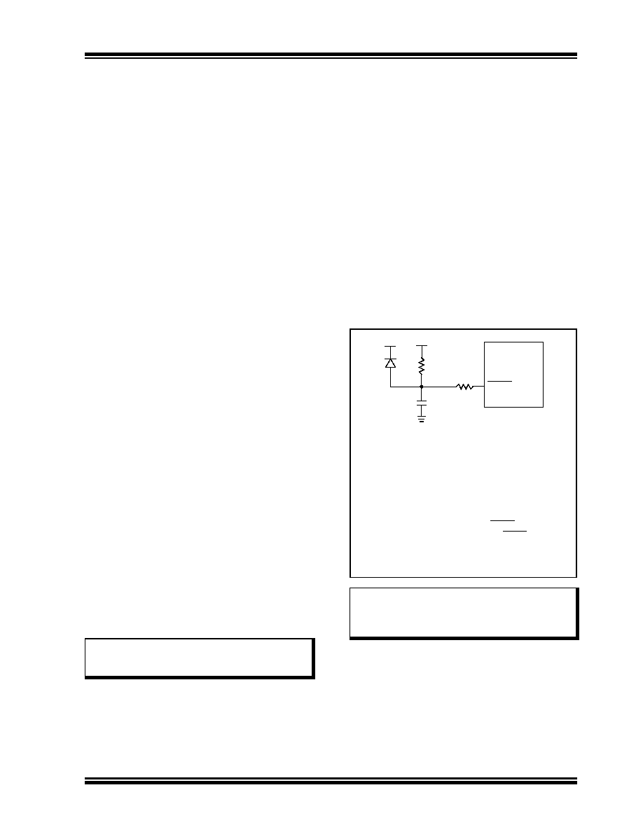
FIGURE 21-6:
EXTERNAL POWER-ON
RESET CIRCUIT (FOR
SLOW VDD POWER-UP)
Note:
The BOR voltage trip points indicated here
are nominal values provided for design
guidance only.
Note:
Dedicated supervisory devices, such as
the MCP1XX and MCP8XX, may also be
used as an external Power-on Reset
circuit.
Note 1:
External Power-on Reset circuit is required
only if the VDD power-up slope is too slow.
The diode D helps discharge the capacitor
quickly when VDD powers down.
2:
R should be suitably chosen so as to make
sure that the voltage drop across R does not
violate the device’s electrical specification.
3:
R1 should be suitably chosen so as to limit
any current flowing into MCLR from external
capacitor C, in the event of MCLR pin break-
down, due to Electrostatic Discharge (ESD)
or Electrical Overstress (EOS).
C
R1
R
D
VDD
dsPIC30F
MCLR
发布紧急采购,3分钟左右您将得到回复。
相关PDF资料
DSPIC30F4013-30I/ML
IC DSPIC MCU/DSP 48K 44QFN
DSPIC30F5013-30I/PT
IC DSPIC MCU/DSP 66K 80TQFP
DSPIC30F5015-30I/PT
IC DSPIC MCU/DSP 66K 64TQFP
DSPIC30F6010-20E/PF
IC DSPIC MCU/DSP 144K 80TQFP
DSPIC30F6010A-30I/PF
IC DSPIC MCU/DSP 144K 80TQFP
DSPIC30F6013A-30I/PF
IC DSPIC MCU/DSP 132K 80TQFP
DSPIC30F6014-30I/PF
IC DSPIC MCU/DSP 144K 80TQFP
DSPIC33EP512MU814-I/PL
IC DSC 16BIT 512KB 144LQFP
相关代理商/技术参数
DSPIC30F4011-30I/P
功能描述:数字信号处理器和控制器 - DSP, DSC 16bit Signal Cntrlr RoHS:否 制造商:Microchip Technology 核心:dsPIC 数据总线宽度:16 bit 程序存储器大小:16 KB 数据 RAM 大小:2 KB 最大时钟频率:40 MHz 可编程输入/输出端数量:35 定时器数量:3 设备每秒兆指令数:50 MIPs 工作电源电压:3.3 V 最大工作温度:+ 85 C 封装 / 箱体:TQFP-44 安装风格:SMD/SMT
DSPIC30F4011-30I/PT
功能描述:数字信号处理器和控制器 - DSP, DSC 16 Bit MCU/DSP 30M 48KB FL RoHS:否 制造商:Microchip Technology 核心:dsPIC 数据总线宽度:16 bit 程序存储器大小:16 KB 数据 RAM 大小:2 KB 最大时钟频率:40 MHz 可编程输入/输出端数量:35 定时器数量:3 设备每秒兆指令数:50 MIPs 工作电源电压:3.3 V 最大工作温度:+ 85 C 封装 / 箱体:TQFP-44 安装风格:SMD/SMT
DSPIC30F4011T-20E/ML
功能描述:数字信号处理器和控制器 - DSP, DSC 16 Bit MCU/DSP 44LD 20M 48KB FL RoHS:否 制造商:Microchip Technology 核心:dsPIC 数据总线宽度:16 bit 程序存储器大小:16 KB 数据 RAM 大小:2 KB 最大时钟频率:40 MHz 可编程输入/输出端数量:35 定时器数量:3 设备每秒兆指令数:50 MIPs 工作电源电压:3.3 V 最大工作温度:+ 85 C 封装 / 箱体:TQFP-44 安装风格:SMD/SMT
DSPIC30F4011T-20E/PT
功能描述:数字信号处理器和控制器 - DSP, DSC 16 Bit MCU/DSP 20M 48KB FL RoHS:否 制造商:Microchip Technology 核心:dsPIC 数据总线宽度:16 bit 程序存储器大小:16 KB 数据 RAM 大小:2 KB 最大时钟频率:40 MHz 可编程输入/输出端数量:35 定时器数量:3 设备每秒兆指令数:50 MIPs 工作电源电压:3.3 V 最大工作温度:+ 85 C 封装 / 箱体:TQFP-44 安装风格:SMD/SMT
DSPIC30F4011T-20I/ML
功能描述:数字信号处理器和控制器 - DSP, DSC DIG SIG CONTR RoHS:否 制造商:Microchip Technology 核心:dsPIC 数据总线宽度:16 bit 程序存储器大小:16 KB 数据 RAM 大小:2 KB 最大时钟频率:40 MHz 可编程输入/输出端数量:35 定时器数量:3 设备每秒兆指令数:50 MIPs 工作电源电压:3.3 V 最大工作温度:+ 85 C 封装 / 箱体:TQFP-44 安装风格:SMD/SMT
DSPIC30F4011T-20I/PT
功能描述:数字信号处理器和控制器 - DSP, DSC 16 Bit MCU/DSP 20M 48KB FL RoHS:否 制造商:Microchip Technology 核心:dsPIC 数据总线宽度:16 bit 程序存储器大小:16 KB 数据 RAM 大小:2 KB 最大时钟频率:40 MHz 可编程输入/输出端数量:35 定时器数量:3 设备每秒兆指令数:50 MIPs 工作电源电压:3.3 V 最大工作温度:+ 85 C 封装 / 箱体:TQFP-44 安装风格:SMD/SMT
DSPIC30F4011T-30I/ML
功能描述:数字信号处理器和控制器 - DSP, DSC 16 Bit MCU/DSP 44LD 30M 48KB FL RoHS:否 制造商:Microchip Technology 核心:dsPIC 数据总线宽度:16 bit 程序存储器大小:16 KB 数据 RAM 大小:2 KB 最大时钟频率:40 MHz 可编程输入/输出端数量:35 定时器数量:3 设备每秒兆指令数:50 MIPs 工作电源电压:3.3 V 最大工作温度:+ 85 C 封装 / 箱体:TQFP-44 安装风格:SMD/SMT
DSPIC30F4011T-30I/PT
功能描述:数字信号处理器和控制器 - DSP, DSC 16 Bit MCU/DSP 30M 48KB FL RoHS:否 制造商:Microchip Technology 核心:dsPIC 数据总线宽度:16 bit 程序存储器大小:16 KB 数据 RAM 大小:2 KB 最大时钟频率:40 MHz 可编程输入/输出端数量:35 定时器数量:3 设备每秒兆指令数:50 MIPs 工作电源电压:3.3 V 最大工作温度:+ 85 C 封装 / 箱体:TQFP-44 安装风格:SMD/SMT